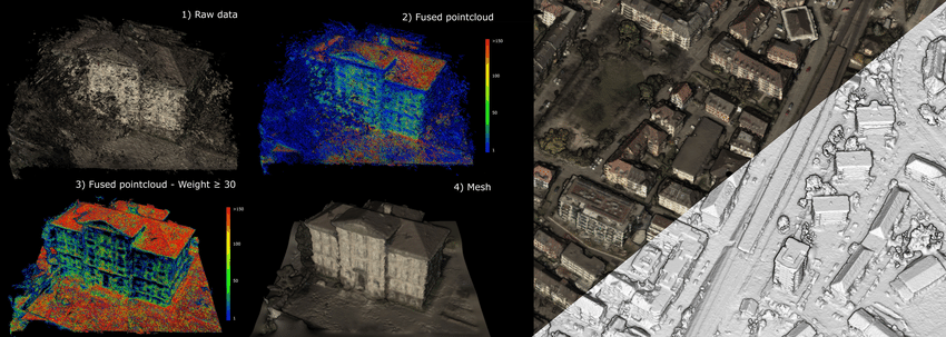
Based on a successful AKT (Accelerated Knowledge Transfer) project between the National Subsea Centre and SABRE Advanced 3D, the Net Zero Operations team developed an innovative two-stage calibration solution for image-point cloud fusion. The software provided 2D-to-3D “big data” mapping, aligning point cloud data with colour and spatial information from 06 camera images with different perspective angle viewpoints, resolving visual object interests during overlay and computing power resource usage while providing a cost-effective solution. The software will help surveying and inspection service companies, covering subsea/marine, renewables, infrastructure development and maintenance, utility mapping, roads and highways, geospatial, GIS/geomatics, mining and oil & gas.
In this article, our Net Zero Operations Senior Research Assistant, Truong Dang, explains how the team tackled the problem of image-point cloud fusion and provided a solution.
3D Mapping
3D mapping refers to the process of creating three-dimensional representations of real-world objects, environments or structures. By creating an accurate representation of real-world objects, 3D mapping can enable professionals to visualise and plan their projects more effectively, bringing new levels of detail and understanding to their work. The 3D data is usually recorded using LiDAR (Light Detection and Ranging), which is a method that uses light in the form of a pulsed laser to measure ranges (variable distances) from the camera to different objects. These light pulses help generate precise, three-dimensional information about the shape of the environment. The recorded data provided by LiDAR is called a 3D point cloud.
3D Point Cloud
While 3D point cloud provides geometry information of the environment, much of the scenic and texture information is lost in the process. For example, when a 3D object is recorded using LiDAR, the corresponding 3D point cloud might show the object's shape with the addition of a camera, this can provide RGB true colour for the object. Or if there is a light source close by, there would be a shadow below, but it would not show on the 3D point cloud. On the other hand, traditional 2D cameras do not provide geometric understanding and surrounding environment object information. The process of combining these two sources of information is called image-point cloud fusion.
Image-Point Cloud Fusion
Image-point cloud fusion refers to matching between the two sources. Image-point cloud fusion has great applications in creating links between the different data to help further optimise the use and handling of the data for analysis and generation of outputs. For example, if one has an image which contains a car, they can draw a bounding box which contains that car, now to fuse between the image and the 3D point cloud, they have to draw another bounding box in the 3D point cloud and match the two so that the car's position in both the image and the 3D point cloud is known.
Project Background
SABRE Advanced 3D, a leading provider of infrastructure 3D solutions, faced significant challenges in optimising and combining 3D data with images. These challenges impacted their ability to make precise decisions in infrastructure planning, 3D mapping, navigating and maintenance.
The Proposed Approach
To address these issues, SABRE Advanced 3D collaborated with the Net Zero Operations research team to develop an innovative two-stage calibration network for 3D point cloud fusion. The project aimed to overcome existing limitations in fusing and combining 3D data with image data and to optimise the alignment in 2D-to-3D point cloud data with colour and spatial information from 06 camera images with different camera angle perspective views.
Stage 1: Point Cloud Overlay Fusion
The first stage focused on accurately mapping 2D pixels to 3D coordinates using intrinsic and extrinsic parameters along with depth map information. This process involved:
Converting each pixel's 2D coordinates to 3D coordinates using depth values and calibrated transformation matrices. Aligning 2D-to-3D data by synchronising time stamps and intelligent augmentation of images to improve overlay alignment. Extracting prominent feature points and contour lines for efficient visualisation in 3D space.
Stage 2: Refinement and Filtering
The second stage aimed to refine the results from Stage 1 and enhance scene visualisation:
- Implementing a novel 06-image-stitching and mapping mechanism to establish a robust reference frame for filtering
- Applying advanced filtering techniques to remove noise and outliers, distinguishing valid 3D points based on expected spatial relationships
- Utilising benchmark deep learning networks to adapt to dynamic environments with moving objects
Results and Impact
The developed 2D-3D visualisation software tool capabilities yielded significant improvements for SABRE Advanced 3D:
Enhanced accuracy: The fusion method provided more precise spatial representation, enabling better decision-making in infrastructure planning.
Cost-effectiveness: The software-defined solution tool delivered offers a more affordable alternative to expensive hardware upgrades.
Optimised visualisation: Advanced filtering, mapping and refinement techniques resulted in a clearer form of linkage between 3D data with 2D imagery for optimised visualisations which allows better user interaction and engagement.
With this innovative approach, SABRE Advanced 3D improved its “big data” operational efficiency and effectiveness, and positioned itself to be a leader with its application-specific software tool for advanced spatial data solutions, meeting the growing market demand for precise 3D visualisation in infrastructure development.
Next-Level Adaptability: In future work, the tool will be capable of handling dynamic environments with moving objects, expanding its applicability across various projects.
To discover more about how our Net Zero Operations team is solving real-world problems, view our dedicated Net Zero Operations webpage or Projects page.


